Summary

The main issue recently has been achieving a low-impedance ground, so that the ‘standing wave’ cavity is formed between the top of the Tesla transformer and Earth, rather than being formed between the top and bottom of the Tesla transformer.
When an impedance-matching transformer is used to drive an Extra coil, the system impedance of the setup has three components:
- Drive impedance of the Tesla Extra coil.
- Impedance of the matching transformer.
- Impedance of the ground.
All of these three factors are related to each-other, and it seems that one poor-quality component will hurt performance on the others.
For example, if the ground has a very low impedance (2 ohm) but the coil has a high drive impedance (50 ohm), the coil will drag the system impedance up to some number between the two (perhaps 25 ohms).
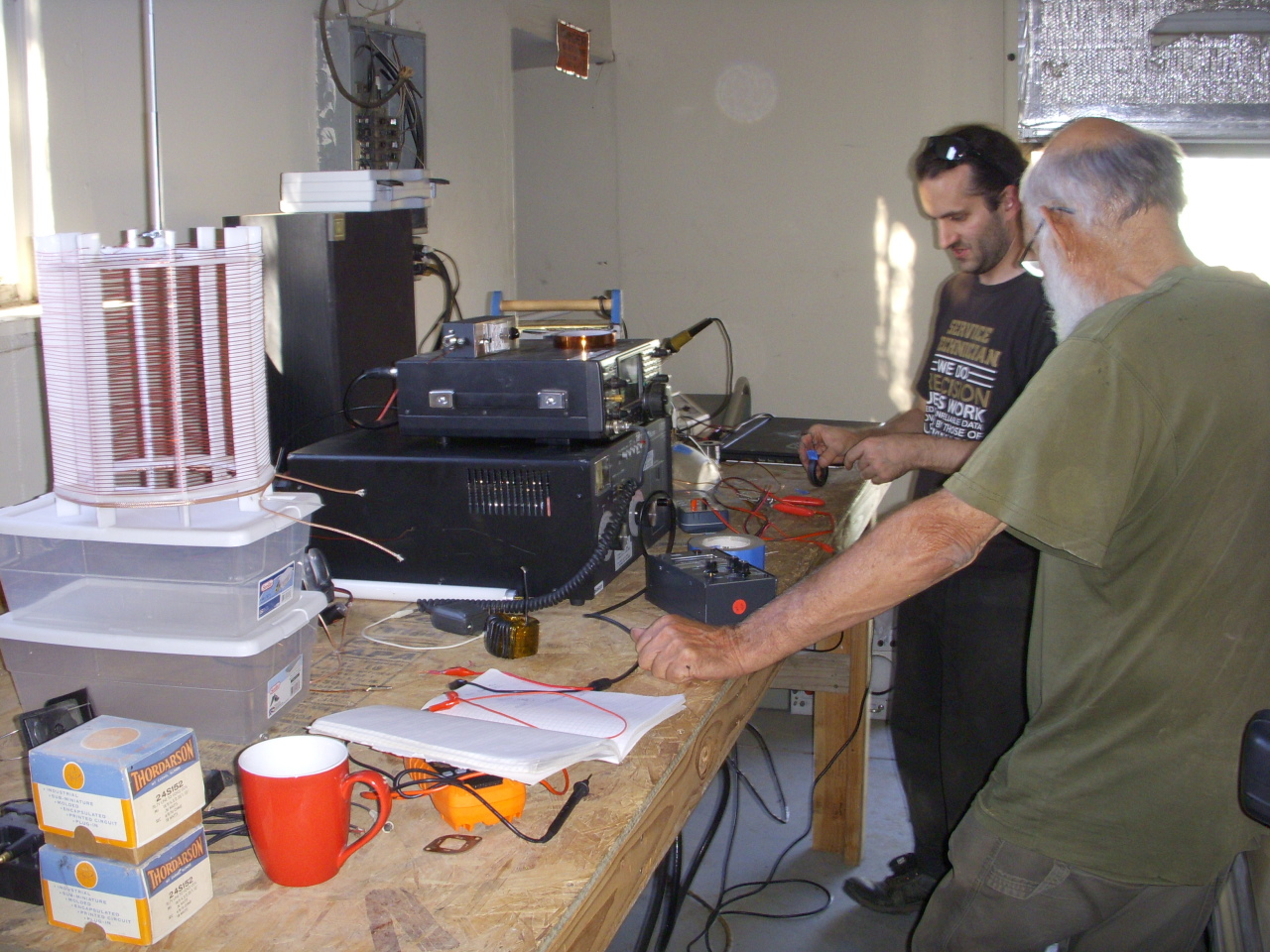
Experimental setup
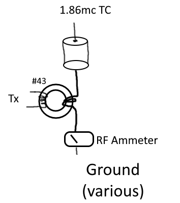
Transceiver: Icom 100w HF transceiver
Frequency: 160m band, approx 1.86mc for all.
Coil: 160m extra coil with adjustable mast. Measured drive impedance with VNA ~35 ohms @ 1.86mc. ~9.5in height + diameter, ~150ft #20 awg wire, Magnification factor ~100.
Primary matching network: MFJ-969 Antenna tuner.
Matching transformer: varies; best match recorded for each setup.
Ground current measurement: 0-5 amp RF Ammeter (thermocouple type).
Experiments

Test #1: EPD Labs Indoors.
10ft ground lead attached to two 10,000+ gallon underground tanks. Measured DC resistance less than 1 ohm to electrical ground.
Result: Peak ground current 1.8 amperes @ 50 watts input.
50w / 1.8a = 27.7 volts
27.7v / 1.8a = 15.43 ohms total system impedance.
Test #2: EPD Labs Outdoors.
Coil directly atop 10,000gal underground tank, 3ft of multiple low-inductance leads to the system.
Result: ground current 2.1 amperes @ 50 watts input.
50w / 2.1a = 23.8 volts
23.8v / 2.1a = 11.33 ohms total system impedance.

Test #3: Hakasays Shop Indoors good ground.
Coil directly atop a 28ft 1″ diamete galvanized steel pipe, 14ft beneath water table. Measured DC resistance 2.2 ohms to nearby electrical ground.
Result: ground current 1.3 amperes @ 100 watts input.
100w / 1.3a = 77 volts
77v / 1.3a = 59.17 ohms total system impedance.

Test #4: Hakasays Shop Indoors poor ground.
Coil attached via 6ft of 1in copper strap to 8ft copper ground rod, 7.5ft driven into dense clay soil. Measured DC resistance ~50 ohms to nearby electrical ground.
Result: ground current 1.25 amperes @ 100 watts input.
100w / 1.25a = 80 volts
80v / 1.25a = 64 ohms total system impedance.

Test #5: Hakasays Outdoor ocean strap ground.
25ft ground strap tossed directly into the ocean.
Result: ground current 1.2a @ 50 watts input.
50w / 1.2a = 41.7 volts
41.7v / 1.2a = 34.72 ohms total system impedance.

Test #6: Hakasays Outdoor ocean plate ground.
25ft ground strap tossed directly into ocean, also attached to aluminum sheet, approx 2sqft submerged.
Result: ground current 1.26 amperes @ 50 watts input.
50w / 1.26a = 39.7 volts
39.7v / 1.26a = 31.49 ohms total system impedance.
Tentative conclusions:
Ground electrode surface area appears to play a massive role in achieving a low-impedance ground, at least at these frequencies.
This is most evident by the near-identical results received with the ~2 ohm pipe ground and the ~50 ohm pipe ground.
(Note: photos reflect the setup conditions and not necessarily the exact coil under test. All tests were performed with the same Tesla Extra coil)